
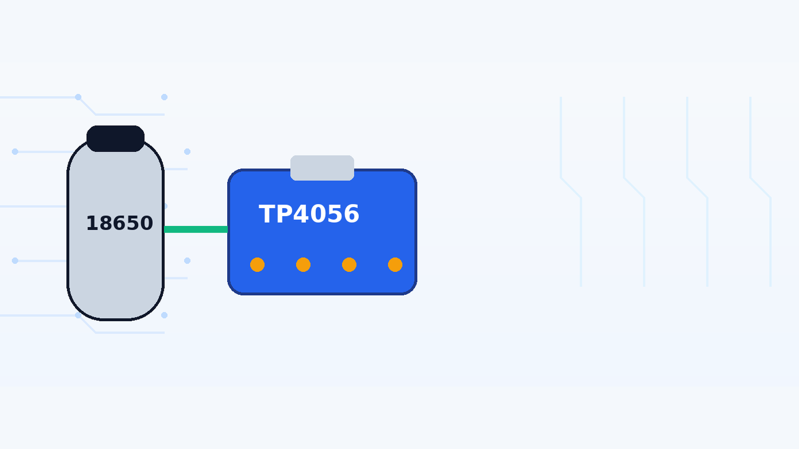

The TP4056 is a simple and inexpensive way to charge a single 3.7 V lithium-ion cell, including common 18650 batteries, from a 5 V supply. The important part is using the correct battery chemistry, wiring the polarity (قطبیت) correctly, and understanding that a TP4056 charger is designed for one Li-ion/LiPo cell, not a multi-cell series battery pack.
Safety warning: Lithium-ion cells can deliver very high current and may vent, overheat or catch fire if shorted, reversed, physically damaged or charged incorrectly. Do not use swollen, leaking, punctured or badly damaged cells. Work on a non-flammable surface, verify polarity before power-up, and never leave an experimental charging setup unattended.
What is a TP4056 module?
The TP4056 is a linear charger IC for a single lithium-ion cell. It uses a constant-current/constant-voltage (CC/CV) charging process. During the first part of charging, the circuit supplies a controlled current. As the battery approaches its final charge voltage, the charger holds the voltage near 4.2 V and the current gradually falls. The IC then terminates charging when the current falls to its termination threshold.
According to the manufacturer, the TP4056 provides a fixed 4.2 V charge voltage, programmable charge current up to 1 A, thermal regulation (حرارتی کنٹرول), automatic recharge, charge-status outputs and a low-current pre-charge mode for a deeply discharged cell. These features make it useful in small battery-powered projects, but the board around the IC determines which connectors and protection functions you actually get.
Important: charger-only vs protected TP4056 boards
Two boards can both be sold as “TP4056 modules” and still behave differently. A basic charger-only board normally provides the input and battery connection. A protected version adds a separate battery-protection circuit (حفاظتی سرکٹ), commonly with extra components and separate load/output pads.
| Board type | Typical connections | What it means |
|---|---|---|
| Charger-only | IN+/IN- and BAT+/BAT- (labels vary) | Charges the cell. Do not assume it also protects the battery from every over-discharge, over-current or short-circuit condition. |
| Charger + protection | Input plus B+/B- and OUT+/OUT- on many common boards | Battery connects to B+/B-. The load normally connects to OUT+/OUT-. Protection is provided by additional circuitry, not by the TP4056 charging IC alone. |
Parts and tools
- TP4056 charging module suitable for one Li-ion/LiPo cell
- One compatible 3.7 V nominal lithium-ion cell, such as an 18650
- Stable 5 V USB power source
- Battery holder or properly insulated battery leads
- Digital multimeter
- Soldering iron and heat-shrink tubing if permanent wiring is required
Step 1: Check the battery before connecting anything
Read the printing on the cell. The guide is for a conventional single-cell Li-ion/LiPo battery that charges to 4.2 V. Do not use the same procedure for LiFePO4, NiMH, lead-acid or a multi-cell series pack because those batteries require different charging methods.
Inspect the cell for swelling, corrosion, torn insulation, dents or heat damage. Measure its voltage with a multimeter. A cell at a very low voltage may be damaged or may need special assessment rather than simply being connected to a charger module.
Step 2: Identify the terminals on your exact TP4056 board
Do not rely only on the board colour or a product photo. Read the silkscreen labels on the module in front of you. Common protected modules use the following labels:
- IN+ / IN-: 5 V input when the board also exposes solder pads for the USB input.
- B+ / B-: battery positive and battery negative.
- OUT+ / OUT-: protected output for the load on modules that include a protection stage.
Some charger-only boards use BAT+ / BAT- and do not provide OUT terminals. If your board does not match the labels above, follow the markings and documentation for that board rather than copying a wiring diagram from a different module.
Step 3: Connect the 18650 with correct polarity
Connect the positive side of the cell to the board’s battery-positive terminal and the negative side to battery-negative. Check the connection with a multimeter before applying input power. Reverse polarity can damage the module and can create a dangerous high-current fault at the battery.
Step 4: Apply a stable 5 V input
Power the module from a stable 5 V USB source. The TP4056 IC itself is specified for a wider input range, but common modules are normally intended to be used around 5 V. Because this is a linear charger, the voltage difference between the input and battery is converted into heat while current is flowing. Using an unnecessarily high input voltage increases power dissipation and may make the charger much hotter.
Step 5: Understand the LED indicators
Most TP4056 modules use two status LEDs, but LED colours are not guaranteed across every board. One status output indicates that charging is active, and the other indicates standby/charge completion. Use the markings or seller documentation for the exact board instead of assuming that red always means charging and blue always means full.
Step 6: Measure the charging process
Measure the battery voltage before charging and again as the cell approaches full charge. A normal single-cell Li-ion charger based on TP4056 regulates the final voltage around 4.2 V. The current should eventually taper as the charger moves from constant-current to constant-voltage operation.
If you also measure charge current, remember that the value depends on the PROG resistor fitted to the board. The TP4056 supports programmable current up to about 1 A, but “TP4056 module” does not automatically mean that every board should charge every battery at 1 A. The allowed current must also be appropriate for the battery manufacturer’s specification.
Why does a TP4056 module get hot?
Some warmth is expected because the TP4056 is a linear charger. A simple approximation for the heat dissipated by the charger is the voltage dropped across it multiplied by the charging current. For example, the charger works harder thermally when a 5 V supply is feeding a low-voltage cell at high current than when the battery is already near full voltage. The IC includes thermal regulation and can reduce charging current when it becomes too hot, but persistent excessive heat is still a reason to check input voltage, charge current, soldering, airflow and battery condition.
Can I use the device while the battery is charging?
Do not assume that a basic TP4056 board provides proper power-path or load-sharing control. A load connected to the battery while charging can change the current seen by the charger and may interfere with normal charge termination. For a product that must operate continuously while charging, use a circuit designed with proper power-path management rather than treating the TP4056 board as a complete UPS.
Common problems and troubleshooting
| Symptom | Check first | Possible explanation |
|---|---|---|
| No LED / no charging | Confirm 5 V input and ground at the board | Bad cable/supply, damaged USB connector, broken solder joint or failed module |
| Charging LED stays on for a very long time | Measure battery voltage and, if possible, charge current | Large-capacity cell, low programmed current, ageing cell, load connected during charging or battery problem |
| Module becomes very hot | Check input voltage and charge current | Linear-charger heat, excessive current for board cooling, poor thermal contact or battery drawing abnormal current |
| Battery never reaches about 4.2 V | Check cell condition and actual current | Weak/damaged cell, inadequate supply, charger limiting thermally or board fault |
| Protected board has battery voltage at B+/B- but no output | Check OUT+/OUT- and protection state | Protection circuit may have tripped because of low voltage, over-current or short circuit |
| Battery gets hot | Disconnect power and investigate | Cell damage, excessive charge rate, internal fault or incorrect battery type; do not continue charging a hot/damaged cell |
Common mistakes to avoid
- Connecting the battery backwards.
- Charging two or more series cells with a single TP4056.
- Assuming every blue/red TP4056 board includes battery protection.
- Using a damaged or unknown lithium-ion cell.
- Assuming the default module current is safe for every cell capacity.
- Using a higher input voltage just because the IC absolute/operating specification permits it.
- Connecting a permanent load and assuming charge termination will still work correctly.
- Leaving an experimental lithium charging setup unattended.
Frequently asked questions
Can a TP4056 charge two 18650 cells?
It is designed as a single-cell charger. Two cells permanently connected in parallel behave electrically as one cell group but introduce cell-matching and safety issues; cells in series require a different charger and battery-management arrangement. For beginners, use one cell with one TP4056 module.
What voltage is a fully charged 18650 cell?
A conventional 4.2 V Li-ion 18650 cell is charged to about 4.2 V. Always check the battery manufacturer’s specification because not every lithium chemistry uses the same charge voltage.
What input should I use?
A stable 5 V USB supply is the normal choice for common TP4056 modules. Avoid assuming that every module can safely dissipate the heat produced at higher input voltages.
Why does the charging current fall near full charge?
That is part of normal CC/CV charging. Once the battery reaches the regulated voltage region, the charger holds voltage while current tapers down.
Does TP4056 include over-discharge protection?
The TP4056 IC is a charger. Some modules add separate protection components, while others do not. Look at the exact board and its circuit/labels.
Can I charge a LiFePO4 cell with TP4056?
A standard TP4056 is intended for a 4.2 V Li-ion charge profile, so it is not the correct charger for a typical 3.6/3.65 V LiFePO4 cell. Use a charger designed for that chemistry.
Final takeaway
The TP4056 is useful because it puts the essential single-cell Li-ion charging process into a very small circuit. The safe way to use it is equally simple: identify the exact board, use one compatible cell, verify polarity, use a stable 5 V input, choose an appropriate charging current and confirm the result with a meter. The LED is helpful, but the measurements are what turn a quick project into a reliable electronics tutorial.