
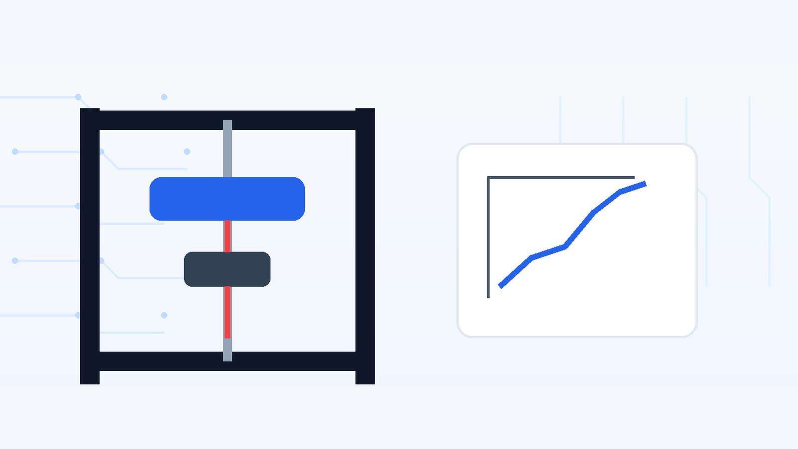

A universal testing machine (UTM) applies a controlled mechanical load to a specimen and measures how the specimen responds. Commercial UTMs can perform tensile, compression, bend, peel, puncture, shear and other mechanical tests. A small Arduino-based machine follows the same basic measurement idea, but with much simpler hardware and lower force capability.
The useful engineering challenge is not simply making a motor pull a sample until it breaks. The machine must measure force, measure or estimate displacement, keep the loading path aligned, move at a controlled rate, log synchronized data, and remain safe when a specimen suddenly fractures.
What does a universal testing machine measure?
At its simplest, a UTM answers two questions at the same time: how much force is being applied, and how much the specimen is deforming (شکل میں تبدیلی). From those measurements, and from the original specimen dimensions, you can calculate useful engineering quantities such as stress, strain, stiffness and ultimate tensile strength.
| Measurement | What it tells you | Typical sensor / source |
|---|---|---|
| Force | How strongly the machine is pulling or pushing the specimen | Load cell + instrumentation ADC such as HX711 |
| Crosshead position | How far the moving grip or platen has travelled | Stepper count, encoder, linear potentiometer or linear scale |
| Specimen strain | How much the defined gauge length of the specimen changes | Extensometer or optical / independent displacement measurement |
| Time / test speed | How fast the test is being performed | Arduino timer + commanded or measured motion |
| Specimen dimensions | Original cross-sectional area and gauge length | Caliper / micrometer + test setup data |
Key distinction: crosshead travel is not automatically the same as specimen elongation. Professional tensile-testing guidance uses dedicated strain measurement because machine compliance, grip seating and slip can contaminate a strain value calculated only from crosshead movement.
Typical Arduino UTM architecture
The exact hardware varies from one build to another, but a practical low-force Arduino UTM usually contains the following functional blocks. Treat this as a recommended architecture, not a claim that every item below is visible in the ElectroCareHub video.
| Subsystem | Typical hardware | Job |
|---|---|---|
| Load frame | Rigid single- or dual-column structure | Carries reaction force without excessive bending or twisting |
| Actuator | Stepper motor + driver + lead screw / ball screw | Moves the crosshead at a controlled speed |
| Guidance | Linear rods, bearings or rails | Keeps crosshead movement straight and reduces side load |
| Force sensor | S-type, beam or other suitable load cell | Converts tension/compression into a tiny bridge-voltage change |
| Signal conditioning | HX711 or another instrumentation ADC | Amplifies and digitizes the load-cell bridge signal |
| Controller | Arduino Uno or similar board | Reads sensors, commands motion, handles limits and logs data |
| Displacement sensing | Encoder, linear potentiometer, digital scale or extensometer | Measures movement / specimen elongation |
| Specimen fixtures | Tensile grips or compression platens | Transfers load into the specimen |
| Safety | Limit switches, guards, E-stop, current/force limits | Stops dangerous overtravel or overload |
How the load cell and HX711 measure force
Most small electronic load cells use strain gauges connected as a Wheatstone bridge. When the load cell bends or stretches slightly, the resistance of the gauges changes and the bridge produces a very small differential voltage. The HX711 is designed to amplify and digitize signals from load cells and strain gauges, which is why it appears so often in Arduino weighing and force-measurement projects.
The HX711 is commonly described as a 24-bit ADC. That is the converter word length, not a promise that your completed machine has 24-bit force accuracy. Real resolution is limited by mechanical vibration, electrical noise, load-cell sensitivity, mounting, temperature, drift and the quality of calibration. Adafruit documents selectable output rates of 10 or 80 samples per second on its HX711 implementation, while SparkFun shows the standard bridge-to-HX711-to-microcontroller connection.
Choose the load cell for the expected force
- Select a capacity comfortably above the highest force you expect, including transient overload, but do not choose a sensor ten or one hundred times larger than necessary if you want good low-force resolution.
- For tension testing, an S-type load cell is convenient because it can be mounted inline and many S-type designs can measure both tension and compression.
- A bar-type load cell must be mounted in the orientation intended by its manufacturer. Clamping both ends incorrectly can make the reading nonlinear or simply wrong.
- Keep the force path centered through the load cell. Side load and bending moments reduce accuracy and can damage the sensor.
- Use mechanical stops or software force limits so a broken specimen or runaway motor does not drive the load cell beyond its rated capacity.
Never use the load-cell rated capacity as the frame design limit. The frame, grips, bolts, lead screw, couplers and bearings all need their own safety margin, and a specimen can release stored energy suddenly when it fractures.
How to calibrate the force measurement
Calibration (کیلیبریشن) converts raw HX711 counts into a force value. A good calibration is not one random weight followed by a convenient multiplication factor. Use several known loads across the part of the range you actually intend to use.
- Warm up the electronics briefly, leave the machine unloaded and tare the reading to establish zero.
- Apply a known mass or reference force through the same mechanical load path used during a real test.
- Record the raw reading after it settles. Repeat at several points, for example near 10%, 25%, 50%, 75% and 90% of the intended working range when safe and practical.
- Convert known mass to force when reporting in newtons: F = m × g. For ordinary workshop calculations, g ≈ 9.81 m/s².
- Fit / calculate the calibration factor and then verify it with at least one different reference load that was not used to create the factor.
- Load and unload the sensor to check hysteresis. Repeat the sequence to judge repeatability (بار بار ایک جیسے نتائج).
- Save the calibration factor together with the load-cell serial number / capacity and the date. Recalibrate after mechanical changes, overloads or unexplained drift.
| Calibration check | Why it matters | What a problem looks like |
|---|---|---|
| Zero stability | Confirms tare and drift are under control | Reading slowly walks while nothing is loaded |
| Multi-point linearity | Checks scale factor across the range | Correct at one weight, wrong at higher loads |
| Repeatability | Shows whether setup gives consistent results | Same reference load gives noticeably different readings |
| Hysteresis | Compares loading vs unloading | Reading depends on direction of force change |
| Off-axis sensitivity | Reveals mounting/alignment issues | Reading changes when the fixture is nudged sideways |
Measuring displacement: stepper travel vs real specimen strain
A stepper-driven lead screw gives a convenient estimate of crosshead motion. If the lead screw moves P millimetres per revolution, the motor has S full steps per revolution, and the driver uses M microsteps per full step, then the nominal motion per microstep is:
distance per microstep = P / (S × M)
That value describes commanded machine movement. It does not automatically describe the change in specimen gauge length. Backlash, lead-screw error, elastic deflection of the frame, grip deformation and slip all sit between the motor command and the specimen.
| Method | Advantages | Limitations |
|---|---|---|
| Stepper count only | Very cheap; no extra sensor; useful for coarse crosshead position | Does not detect missed steps; includes backlash, frame compliance and grip effects |
| Rotary encoder | Can confirm screw / motor rotation | Still measures drive motion rather than specimen deformation |
| Linear potentiometer / encoder | Measures crosshead or fixture travel directly | Still includes machine / grip compliance unless attached across specimen gauge length |
| Clip-on extensometer | Direct gauge-length strain measurement; good for modulus/yield work | More complex and must suit specimen travel and force environment |
| Optical / video extensometer | No contact with specimen; useful for fragile/high-elongation samples | Requires good optics, calibration, markers and image processing |
From force and elongation to stress and strain
Force and movement are only the raw measurements. Material properties depend on the original specimen geometry.
| Quantity | Equation | Meaning |
|---|---|---|
| Engineering stress, σ | σ = F / A₀ | Applied force divided by original cross-sectional area |
| Engineering strain, ε | ε = ΔL / L₀ | Change in gauge length divided by original gauge length |
| Young’s modulus, E | E ≈ Δσ / Δε in the initial linear region | Material stiffness when the test and strain measurement are suitable |
| Ultimate tensile strength | Maximum engineering stress reached | Highest engineering stress before/at necking or fracture |
| Elongation at break | Final extension relative to original gauge length | A measure of ductility, when measured by the specified method |
If force is in newtons and the original cross-sectional area is in square millimetres, stress comes out in N/mm², which is numerically equal to megapascals (MPa). This makes workshop calculations convenient, provided the original width/thickness or diameter is measured carefully.
Do not calculate a “Young’s modulus” from noisy crosshead travel and present it as a material certificate. Instron specifically notes that accurate strain measurement normally requires a dedicated extensometer rather than relying only on crosshead displacement.
A practical tensile-test workflow
- Choose a specimen and test method appropriate to the educational goal. Measure its original width, thickness / diameter and gauge length before loading.
- Inspect the grips, load cell, frame and fasteners. Set software force and travel limits below the weakest safe component rating.
- Install the specimen so its axis lines up with the load cell and crosshead. Poor alignment introduces bending and can cause premature grip-end failure.
- Bring the grips into light contact / minimal preload as appropriate, then tare the force channel. Do not use a large preload just to make the graph start neatly.
- Zero or record the displacement / extensometer reading at the defined starting gauge length.
- Start data logging before motion. Record time, force and displacement from the same test clock.
- Move the crosshead at the planned test speed. Stop automatically at the chosen force, displacement, fracture detection or safety limit.
- Keep hands away from the specimen and drive system while the test is running. Brittle fragments and snapped specimens can become projectiles.
- After the test, save raw data first. Calculate stress/strain from a copy so the original measurements remain available.
- Repeat the test on multiple specimens if you want to discuss repeatability rather than one dramatic break.
What data should the Arduino log?
A useful UTM log should preserve raw measurements and calculated values. Do not save only the final tensile-strength number; that destroys most of the diagnostic value of the test.
| Field | Example unit | Why keep it |
|---|---|---|
| Timestamp / elapsed time | ms or s | Lets you calculate test rate and align sensors |
| Raw HX711 count | counts | Allows later recalibration / debugging |
| Force | N | Primary load measurement |
| Crosshead position | mm | Machine movement and limit tracking |
| Independent extension | mm | Preferred input for specimen strain when available |
| Specimen area A₀ | mm² | Required for engineering stress |
| Gauge length L₀ | mm | Required for engineering strain |
| Stress | MPa | Material-response calculation |
| Strain | dimensionless or % | Material deformation calculation |
| Machine state | IDLE / RUN / STOP / BREAK | Explains where each sample belongs in the test sequence |
Arduino software architecture
The control code should keep measurement, motion and safety separate enough that one slow function does not hide a dangerous condition. A sensible loop looks like this:
- Initialize HX711, position sensor, motor driver, limit switches and serial / SD logging.
- Wait for the operator to confirm the fixture is safe, then tare force and zero position.
- Read force and position at a consistent rate; apply only documented filtering.
- Check hard limits first: E-stop, limit switches, maximum force, maximum travel and sensor faults.
- Command the next motor step / velocity only if all limits are healthy.
- Write synchronized data to serial, SD card or a connected computer.
- Detect end-of-test conditions such as fracture or target displacement and stop motion safely.
- Require an explicit reset before allowing another move after a safety trip.
Motor current should not be powered from an Arduino I/O pin. A stepper motor needs a suitable driver and power supply, with grounding and noise control designed so motor switching does not corrupt the load-cell measurement or reset the microcontroller.
Noise, filtering and sampling rate
A UTM is a dynamic measurement system. Heavy averaging can make a graph look smooth while hiding a real peak load or delaying fracture detection. Too little filtering can turn vibration and electrical pickup into fake “material behavior.”
- Mount the HX711 close enough to the load cell to keep the millivolt-level bridge wiring short, and use shielded / twisted wiring where appropriate.
- Separate stepper-motor power wiring from load-cell signal wiring. Motor drivers are noisy switching devices.
- Choose a sample rate appropriate to test speed. A very slow tensile test may be fine at low sample rate; a fast fracture event can be poorly represented if the data rate is too low.
- Record raw or lightly processed samples when possible, then apply clearly documented analysis filtering later.
- If using averaging, store the method and number of samples so results can be reproduced.
- Do not infer more decimal places than the machine can physically resolve. Display formatting is not measurement accuracy.
Where DIY UTM results commonly go wrong
| Problem | Likely cause | Corrective action |
|---|---|---|
| Force reading drifts at zero | Temperature drift, mechanical preload, noisy supply, sensor creep | Warm up, remove preload, improve wiring, retare and check load-cell mounting |
| Reading is negative when pulling | Signal polarity reversed | Reverse signal leads or change sign in software after confirming wiring |
| Correct at one calibration weight, wrong elsewhere | Poor calibration, nonlinear mounting, overload or mechanical binding | Use multi-point calibration; inspect load path and sensor mounting |
| Graph is very noisy when motor runs | EMI / ground coupling from stepper driver | Separate power/signal wiring, improve grounding/shielding, decouple supplies |
| Arduino resets during motion | Motor supply sag or electrical noise | Use proper motor PSU/driver, grounding and decoupling; do not power motor from Arduino rail |
| Crosshead moves but measured extension is wrong | Backlash, missed steps, frame compliance or grip slip | Add position feedback / extensometer and improve mechanics |
| Specimen always breaks at grip | Grip damage, stress concentration or poor alignment | Use correct grip geometry, alignment and specimen preparation |
| Calculated strength is impossibly high/low | Wrong area units, wrong force units or specimen dimensions | Check N vs kgf and mm² vs m²; remeasure original section |
| Peak force changes strongly between repeats | Misalignment, inconsistent specimens, speed variation or grip slip | Control specimen geometry, alignment and test speed; repeat calibration |
| HX711 reading freezes / becomes erratic | Wiring, library timing, electrical noise or sensor fault | Check DAT/CLK, supply, grounding and code flow; verify with static load |
Safety: a small machine can still injure you
- Guard the lead screw, coupler and moving crosshead. Pinch points can trap fingers even at modest motor torque.
- Use physical travel limit switches. Software limits alone do not protect against a crashed program, disconnected sensor or wrong calibration.
- Add an emergency stop that removes actuator power, not just a software button on the Arduino screen.
- Wear eye protection and use a clear shield when testing brittle plastics, composites, wires or parts that can snap suddenly.
- Do not stand in line with a tensioned specimen. Stored elastic energy is released when it breaks.
- Rate grips, bolts, frame, lead screw and load cell above the planned working load with an appropriate engineering safety margin.
- Stop immediately if the frame bends, fasteners loosen, the load cell goes off-scale or the machine makes abnormal mechanical noise.
Educational machine ≠ certification machine. ASTM E8/E8M, for example, controls tension testing of metallic materials and the determination of properties such as yield strength, tensile strength and elongation. A DIY rig can teach those concepts, but compliance requires far more than calculating the same equations.
DIY Arduino UTM vs commercial universal testing machine
| Area | Arduino DIY machine | Commercial / standards-oriented UTM |
|---|---|---|
| Primary value | Learning, prototyping, comparative experiments | Traceable engineering and quality-control measurements |
| Force capacity | Usually low to moderate and build-dependent | Specified and verified across rated range |
| Frame stiffness / alignment | Depends heavily on fabrication quality | Engineered and characterized for test accuracy |
| Strain measurement | Often crosshead estimate unless extra sensor added | Dedicated extensometers / validated strain systems commonly used |
| Speed control | Stepper-command based; may lack closed-loop verification | Controlled and documented test rates / feedback |
| Calibration | User-created with masses or reference loads | Traceable calibration / verification procedures |
| Safety | Depends on builder discipline | Purpose-designed guards, limits and safety systems |
| Standards compliance | Do not assume | Can be configured / verified for specific standards |
| Cost | Low | Much higher |
Frequently asked questions
Can Arduino make a real universal testing machine?
Arduino can control a useful low-cost materials-testing rig, but the quality of the machine depends more on mechanics, sensing, calibration, alignment, displacement measurement and safety than on the microcontroller itself.
Why use HX711 with a load cell?
A strain-gauge load cell produces a very small differential signal. HX711 provides high-gain differential conversion designed for load-cell / weigh-scale applications and is easy to interface with a microcontroller.
Should force be shown in kg or newtons?
Use newtons for force. Kilograms describe mass. If calibration uses known masses, convert the applied weight to force before reporting engineering results.
Can I calculate tensile strength from load-cell force?
Yes, if you know the maximum force and the correct original specimen cross-sectional area: engineering tensile strength = maximum force / original area. The result is only as good as the force, area and test setup.
Can I calculate strain from stepper motor steps?
You can estimate crosshead displacement, but it is not the same as direct specimen strain. Frame flex, backlash, grip slip and fixture seating introduce error. Use an extensometer or independent gauge-length displacement measurement for serious strain work.
What load cell should I use?
Choose a type suitable for tension/compression as required and a capacity modestly above the expected maximum load. Also consider overload rating, mounting, sensitivity and available calibration references.
Why are my HX711 readings noisy?
Common causes are motor-driver EMI, long unshielded bridge wiring, poor grounding, vibration, unstable supply voltage, excessive averaging settings or an improperly mounted load cell.
How do I calibrate the UTM?
Tare at zero, apply multiple known reference loads through the real load path, calculate the conversion factor, verify with separate reference points, and check repeatability and hysteresis.
Can this machine meet ASTM E8/E8M?
Not automatically. ASTM tension testing depends on specimen geometry, machine and force verification, test rate, alignment, strain measurement and other controlled requirements. A DIY machine should be described as educational unless it has been formally verified for the standard.
Can the same machine do compression tests?
Potentially, if the frame, actuator, load cell and fixtures are designed for compression and correct platens are fitted. Never assume a tension grip or sensor mounting is safe in compression.
How many samples should I test?
One specimen is useful for demonstrating the machine, but it says little about repeatability. For comparisons, test multiple specimens prepared and loaded the same way and report the spread, not only the best-looking curve.
What should I upgrade first for better data?
After safe mechanics and reliable force calibration, add a real displacement / extensometer measurement, improve alignment and frame stiffness, and log synchronized raw data. Those upgrades usually matter more than changing to a faster microcontroller.