
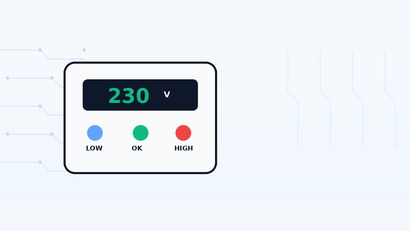

A voltage protector is an automatic monitoring device placed between the electrical supply and a load. Its job is simple to describe but more interesting inside: it continuously watches the supply voltage, compares that measurement with programmed limits, disconnects the load when voltage moves outside the safe window, and reconnects only after the supply returns to an acceptable range.
That makes it useful for homes, shops and small equipment installations where high voltage, low voltage and repeated fluctuations can stress appliances. Many modern DIN-rail units also display voltage, include a reconnect delay, and on some models add current or energy monitoring. The ElectroCareHub video demonstrates the practical device; this article explains the protection logic behind it.
Safety boundary: A voltage protector is connected to mains electricity. Beginners can learn the principle and read the front-panel display/settings, but installation, exposed-terminal work and internal testing should be handled by a qualified electrician or trained technician with the supply isolated and verified safe.
What problem does a voltage protector solve?
Electrical equipment is designed for a specified supply range. A prolonged overvoltage can increase stress and heating in power supplies, motors, capacitors and insulation. Undervoltage can also be harmful, especially to motor-driven loads, because the equipment may draw higher current, fail to start correctly or repeatedly cycle.
A voltage protection relay watches for these sustained abnormal conditions and changes the state of its output relay when a threshold is crossed. Industrial monitoring-relay manufacturers describe the same basic idea: an overvoltage relay acts when voltage rises above a set point, while an undervoltage relay acts when voltage falls below a set point.
Pakistan context: NEPRA performance standards use 400/230 V as nominal distribution voltage and 50 Hz nominal frequency. That is useful context, but it is not a direct instruction for where to set a household protector. Trip limits must suit the actual equipment and the protector manufacturer’s guidance.
The five functional blocks inside a digital voltage protector
| Block | What it does | What you may see in the device |
|---|---|---|
| 1. Voltage sensing | Scales and measures the incoming AC voltage so electronics can evaluate it safely. | Resistor network, sensing circuit, rectification/isolation components depending on design |
| 2. Controller / comparator | Compares measured voltage with the programmed upper and lower limits. | Microcontroller, comparator IC or dedicated monitoring circuit |
| 3. Timing logic | Applies trip delay, restart delay and hysteresis so the relay does not chatter around a threshold. | Firmware/timer circuit and countdown on digital models |
| 4. Switching element | Connects or disconnects the load when protection logic says it is safe or unsafe. | Internal relay, contactor or relay-driving stage |
| 5. User interface | Shows measured voltage and lets the user view or adjust settings. | LED/LCD display, buttons, status indicators |
In simple block form, the signal path is:
AC input → voltage sensing → controller/comparator → protection decision → relay/contactor → protected load
How the working principle operates step by step
1. The protector measures the incoming supply
The sensing circuit converts the mains voltage into a form the controller can measure. A digital model then calculates or estimates the line voltage and shows it on the front display. The important point is that the control electronics do not simply “wait for something to burn”; they continuously compare the measured value with stored limits.
2. The controller checks the voltage window
The device usually has a lower threshold and an upper threshold. While the measured voltage remains between those values, the load is allowed to stay connected. When voltage moves beyond a threshold for the required trip time, the controller commands the output relay to disconnect.
| Supply condition | Controller decision | Typical output state |
|---|---|---|
| Within permitted voltage window | Normal | Relay closed; load connected |
| Above high-voltage threshold | Overvoltage fault | Relay opens; load disconnected |
| Below low-voltage threshold | Undervoltage fault | Relay opens; load disconnected |
| Voltage returns to acceptable range | Recovery check | Delay/countdown before reconnect, depending on settings |
| Persistent or repeated fault | Protection remains active | Load remains disconnected or cycles only according to device logic |
3. The relay disconnects the load
The controller itself handles only a small electrical signal, so a relay or contactor performs the actual switching of the load. When the protector declares a fault, the switching element opens the circuit. When conditions become acceptable again, the relay can close after any configured delay.
A relay rating is not just a decorative number on the case. The current rating, contact category, wiring method and load type must be appropriate for the installation. Large motors and other high-inrush loads may require a correctly rated external contactor instead of relying on a small internal relay.
Why trip delay, reconnect delay and hysteresis matter
Protection systems need to avoid “relay chatter”, where the supply hovers near a threshold and the relay rapidly switches on and off. Two ideas help: delay and hysteresis.
- Trip delay: the abnormal voltage must remain beyond the threshold long enough to be treated as a real fault, depending on the device configuration.
- Reconnect or restart delay: after voltage returns to an acceptable range, the protector waits before reconnecting the load. This gives the supply time to stabilize and can be particularly useful for compressor-based appliances.
- Hysteresis (فرقِ واپسی): the reset point is slightly different from the trip point, preventing rapid switching when voltage sits very close to a limit.
ABB voltage-monitoring relays, for example, use configurable or fixed delays and a defined hysteresis before the output relay changes state again. Consumer protectors implement the same general control idea, though the exact timing and reset behavior vary by model.
What if the protector also shows current?
Some digital protectors combine voltage monitoring with current protection or metering. A unit labelled as a “voltage & current protector” may allow an over-current limit so the relay opens when load current exceeds the programmed value. Other models merely display current without providing the same protection function.
Model-specific rule: do not assume that a display showing amps automatically means the device provides calibrated over-current protection, and do not assume that over-current protection in a smart relay replaces a correctly selected MCB or fuse. Confirm the manual and markings of the exact model.
Voltage protector vs MCB vs RCCB vs surge protector
| Device | Main hazard it addresses | What it normally does not replace |
|---|---|---|
| Over/under-voltage protector | Sustained high or low supply voltage; sometimes over-current on specific models | MCB/fuse, RCCB/RCD, dedicated SPD |
| MCB / fuse | Overload and short-circuit current | Earth-leakage protection and sustained voltage monitoring |
| RCCB / RCD | Residual/earth-leakage current that can indicate electric-shock or insulation fault risk | Overload/short-circuit protection unless combined as an RCBO; voltage-window monitoring |
| SPD / MOV-based surge protection | Very fast transient overvoltage from lightning/switching surges | Sustained high/low voltage disconnection |
| Voltage stabilizer / AVR | Actively adjusts output voltage within its design range | All required fault protection devices |
The distinction between a voltage protector and an SPD is especially important. A voltage relay reacts to a supply that remains too high or too low. A metal-oxide varistor (MOV) in a surge-protection system is designed to clamp very fast transient spikes. One device does not automatically perform the other device’s job.
How should voltage protector settings be chosen?
The safest answer is: from the appliance requirements, local supply characteristics and the protector manufacturer’s instructions. Do not copy another person’s threshold simply because their house also uses 230 V mains.
- Confirm the nominal supply and the acceptable input range printed on the equipment or in its manual.
- Set the high and low limits so normal utility variation does not cause constant nuisance tripping, while abnormal sustained voltage is still disconnected.
- Use a reconnect delay appropriate to the connected load and the protector manufacturer’s recommendations.
- Set any current limit based on the circuit and equipment rating, not merely the largest value the protector allows.
- Do not program a protector beyond the current rating of its relay, terminals, wiring or upstream/downstream protective devices.
Do not rely on a universal threshold such as “set low to X and high to Y” unless the exact protected equipment and device manual justify those numbers.
Where is a voltage protector installed?
DIN-rail models are commonly installed in an electrical distribution enclosure so that the incoming supply passes through, or controls, a protective switching stage before reaching the selected load. The exact arrangement depends on whether the device switches the load directly or drives an external contactor, and whether it protects one circuit or a larger part of the installation.
Installation is electrician work. Correct conductor sizing, terminal torque, breaker/fuse coordination, earthing, neutral arrangement and enclosure safety matter as much as the protector settings. A diagram copied from a different model is not a substitute for the manual supplied with the exact device.
How a technician can test a voltage protector
A proper functional test changes the input voltage in a controlled manner and confirms the actual trip and reset behavior. The safest professional setup uses an isolated/controlled AC source or appropriate test equipment, a suitable load and instruments rated for the mains category involved. The test should verify behavior rather than merely prove that the display lights up.
| Test | What to observe | Pass condition |
|---|---|---|
| Normal-voltage test | Display and relay status | Load connects after the expected startup/reconnect delay |
| High-voltage threshold test | Displayed voltage and relay transition | Relay disconnects at/around configured upper threshold after intended delay |
| Low-voltage threshold test | Displayed voltage and relay transition | Relay disconnects at/around configured lower threshold after intended delay |
| Recovery test | Countdown and relay state | Load reconnects only after voltage returns to acceptable range and delay completes |
| Current-protection test, if supported | Displayed current and trip logic | Behavior matches the model manual and configured current limit |
| Heat/terminal check | Terminal and relay condition under representative load | No abnormal heating, smell, arcing or unstable contact |
Do not create high or low mains voltage by improvised wiring, series lamps, loose neutral tricks or unsafe transformer connections. Controlled mains testing belongs on a properly protected technician bench.
Troubleshooting table
| Symptom | Check first | Likely direction |
|---|---|---|
| Display is completely off | Incoming supply, upstream breaker/fuse, terminal connections | No supply, internal power-supply fault or wiring issue |
| Display works but load never connects | Voltage reading, high/low limits, reconnect timer, relay status | Supply outside window, misconfigured settings or relay/driver fault |
| Protector trips frequently | Actual line voltage, threshold settings, loose neutral, load current | Real supply fluctuation, nuisance settings, wiring issue or over-current |
| Relay chatters near a limit | Measured voltage stability and reset/hysteresis behavior | Unstable supply, poor connection or defective sensing/relay circuit |
| Voltage display looks wrong | Compare with a known-good true-RMS meter | Calibration/sensing issue or waveform-related measurement difference |
| Unit becomes hot | Load current, terminal tightness, contact rating, enclosure temperature | Overload, loose terminal, undersized device or damaged relay |
| Load reconnects too quickly/slowly | Delay setting and model mode | Programmed restart delay or configuration issue |
| Voltage protection works but surge damage still occurs | Check presence/condition of dedicated SPD and earthing | Protector is not a substitute for transient surge protection |
Common mistakes to avoid
- Calling every DIN-rail voltage protector a circuit breaker. Many are monitoring/protection relays, not MCBs.
- Assuming a voltage protector replaces an RCCB/RCD or dedicated surge protective device.
- Copying threshold values from a random video without checking appliance requirements.
- Running a high-inrush or high-current load directly through a relay that is not appropriately rated.
- Ignoring reconnect delay on compressor-based loads.
- Using the displayed voltage as the only calibration reference when troubleshooting; compare with a suitable meter.
- Opening or live-testing a mains protector without isolation, PPE, rated instruments and training.
Frequently asked questions
What is the working principle of a voltage protector?
It measures the incoming supply, compares that voltage with programmed high and low limits, and uses a relay or contactor to disconnect the load when the supply leaves the permitted range. It reconnects after the supply recovers and any configured delay expires.
Does a voltage protector regulate the voltage?
Usually no. A basic over/under-voltage protector disconnects the load; it does not boost low voltage or reduce high voltage like an automatic voltage regulator or stabilizer.
Does a voltage protector replace an MCB?
No. An MCB is primarily for overload and short-circuit protection. A voltage protector monitors supply voltage. Some smart protectors add current limiting, but circuit protection still needs to be designed correctly.
Does it replace an RCCB or RCD?
No. RCCBs/RCDs detect residual leakage current associated with insulation faults and electric-shock risk. A voltage protector does not perform that function.
Is a voltage protector the same as a surge protector?
No. A voltage protector responds to sustained overvoltage or undervoltage. A surge protective device is designed for fast transient spikes. A well-designed installation may use both.
Why does a voltage protector wait before turning the power back on?
The reconnect delay allows the supply to stabilize and prevents immediate cycling. It is particularly useful for loads such as refrigerators and air conditioners, depending on the manufacturer’s recommendations.
Why does my voltage protector keep tripping?
Possible causes include genuine supply fluctuation, thresholds set too tightly, loose or faulty wiring such as a neutral problem, excessive load current on models with current protection, or a defective protector.
What voltage settings should I use in Pakistan?
Pakistan uses nominal 230 V single-phase distribution, but that does not create one universal protector setting. Use the protected equipment’s acceptable input range and the protector manufacturer’s instructions, and have a qualified electrician configure the installation.
Can I test a voltage protector with a normal multimeter?
A multimeter can verify the supply/display reading, but it cannot by itself safely create controlled overvoltage and undervoltage conditions. Full functional testing requires suitable mains test equipment and technician procedures.
Final takeaway
A voltage protector is best understood as an automatic decision-and-switching system. It senses the AC supply, compares it with limits, disconnects the load when voltage becomes unsafe, and reconnects after conditions recover. Delay and hysteresis stop the relay from behaving erratically around the threshold.
The bigger lesson is that electrical protection is layered. Over/under-voltage monitoring, overcurrent protection, earth-leakage protection and transient surge protection address different faults. Combining the correct devices is much safer than expecting one small DIN-rail module to be responsible for every electrical hazard known to humanity.